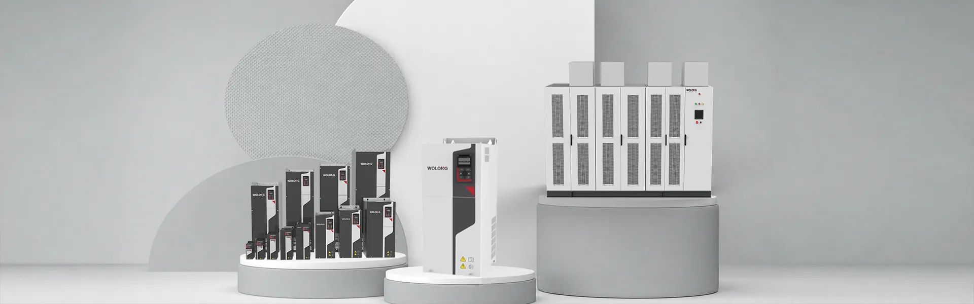
Selecting the right Variable Frequency Drive (VFD) is critical for optimizing energy efficiency, protecting equipment, and ensuring smooth industrial operations. Choosing an improperly sized or specified drive can lead to frequent nuisance trips, motor overheating, or costly system failures.
Here is a comprehensive engineering guide on how to correctly select and size a Variable Frequency Drive for your electric motor system.
1. Understand the Load Profile (The Most Critical Step)
Before looking at drive catalogs, you must understand the mechanical behavior of the machine the motor drives. Loads fall into three primary categories:
Variable Torque (VT): Common in centrifugal pumps, blowers, and fans. The torque requirement increases with the square of the speed. These loads require less torque at lower speeds, making them ideal for energy savings and lighter-duty VFD selection.
Constant Torque (CT): Common in conveyors, positive displacement pumps, crushers, and extruders. The load demands the same amount of torque regardless of speed. These require heavy-duty (HD) rated VFDs capable of delivering full torque at low speeds without overheating.
Constant Horsepower: Common in machine tool spindles and winders. As speed increases, required torque decreases, maintaining a constant power output.
2. Match Current (Amps), Not Just Horsepower (HP)
A common mistake in VFD sizing is selecting the drive purely based on motor horsepower or kilowatt ratings.
Focus on Full Load Amps (FLA): Always size the VFD to meet or exceed the motor's actual rated Full Load Amps (FLA) listed on the motor nameplate, especially for specialized, high-pole (e.g., 6-pole, 8-pole), or older motors, which often draw higher current than standard 2-pole or 4-pole motors.
Account for Overload Capability: Heavy-duty applications require a VFD with a higher overload rating (typically 150% FLA for 60 seconds), whereas light-duty/variable torque applications usually need only 110% to 120% overload capability.
3. Evaluate Environmental and Installation Conditions
Operating conditions significantly impact VFD performance and lifespan. Key environmental factors include:
Ambient Temperature & Altitude: Standard VFDs are rated for ambient temperatures up to 40°C (104°F) and altitudes up to 1,000 meters (3,300 feet). Operating above these limits requires thermal derating of the drive’s current output.
Enclosure Protection (IP/NEMA Ratings): Standard indoor cabinet installations typically use IP20 / NEMA 1 enclosures. Harsh, wet, or washdown environments demand IP66 / NEMA 4X enclosures or dedicated air-conditioned control cabinets to keep dust, moisture, and corrosive elements out.
4. Cable Distance and Power Quality Considerations
The physical layout between the power grid, the VFD, and the motor introduces critical electrical engineering considerations:
Long Lead Lengths (Reflected Wave Phenomenon): When the cable distance between the VFD and the motor exceeds 50–100 feet (15–30 meters), fast switching voltage spikes (dV/dt) can cause motor insulation breakdown. Installing dV/dt filters or sine-wave filters at the output of the VFD is essential for long cable runs.
Harmonic Mitigation: VFDs draw non-linear currents, introducing electrical harmonics back into the facility grid. To comply with grid power quality standards (like IEEE 519), consider active front ends (AFE), line reactors, or passive harmonic filters on the input side.
5. Essential Selection Checklist
When specifying a VFD for a new or retrofit project, ensure you have gathered these five core parameters:
Motor Nameplate Data: Voltage, Frequency, Full Load Amps (FLA), Power Rating (HP/kW), and Service Factor.
Load Type: Variable Torque (Pumps/Fans) vs. Constant Torque (Conveyors/Crushers).
Control Method Required: Simple V/f (Volts per Hertz) control, Sensorless Vector Control, or Closed-Loop Encoder Feedback for ultra-precise speed/torque positioning.
Operating Environment: Temperature, altitude, dust, moisture, and enclosure type.
System Constraints: Cable length to the motor, dynamic braking requirements, and harmonic limits.
Properly evaluating these parameters ensures maximum process reliability, protects motor winding insulation, and yields the highest long-term return on investment.